Damp proofing in Residential Building
Material used for damp proofing


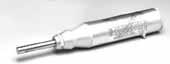
As used by the trade - quick cream is inserted into 12mm holes (400cc mastic tube type illustrated - uses standard skeleton gun)
How to install a damp proof course

Plastic tapered plugs for filling drill holes
Walls and skirting board

Replastering concentrated additive for renders

Air gap membrane is simply fixed with plastic plugs
Material used for damp proofing
1. Property of the material
An effective damp proofing material should have the following properties
1. It should be impervious.
2. It should be strong and durable and should be capable of withstanding both dead as well as live loads without damage.
3. It should be dimensionally stable
4. It should be free from deliquescent salts like sulphates chlorides and nitrates
5. The material should be reasonably cheap.
6. The material should be such that it is possible to carry out leak proof joining work.
2. Classification of material
The materials commonly used to check dampness can be divided into the following four categories
a) Flexible material
Material like bitumen felts (which may be Hessian based or fibre/glass fibre based), plastic sheeting (polythene sheet) etc
b) Semi rigid materials
Materials like mastic asphalts or combination of materials or layers.
c) Rigid materials
Materials like first class bricks, stones, slates, cement concrete etc
d) Grout materials
Grout consists of cement slurry and acrylic based chemical or polymers.
3. Material used for damp proofing
Following are the materials, which are commonly used for damp proofing.
1. Hot bitumen
This is a flexible material and is placed on the bedding of concrete or mortar. This material should be applied with a minimum thickness of 3 mm.
2. Mastic asphalt
This is a semi rigid material and it forms an excellent impervious layer for damp proofing. The good asphalt is very durable and completely impervious material. It can withstand only very slight distortion. It is liable to squeeze out in very hot climates or under very heavy pressure. It should be laid by experienced men of the specially firms.

Mastic asphalt
3. Bituminous felts
This is a flexible material. It is easy to lay and is available in rolls of normal wall width. It is laid on a layer of cement mortar. An overlap of 100 mm is provided at the joints and full overlap is provided at all corners. The laps may be sealed with bituminous if necessary. The bitumen felt can accommodate slight movement. But it is liable to squeeze out under heavy pressure and it offers little resistance to sliding. The material is available in rolls and it should be carefully unrolled, especially in cold weather.
4. Metal sheets
The sheets of lead, copper and aluminium can be used as the membranes of damp proofing.
The lead is a flexible material. The thickness of lead sheets should be such that its weight is not less than 200 N/m2. The lead can be dressed to complex shapes without fracture and it possesses high resistance to sliding action. It is impervious to moisture and it does not squeeze out under ordinary pressure. It resists ordinary corrosion. The surfaces of lead coming in contact with lime and cement are likely to be corroded and hence a coating of bitumen paint of high consistency should protect the metal.
The copper is flexible material. It possesses higher tensile strength than that of lead. It is impervious to atmosphere and it does not squeeze out under ordinary pressure. It possesses high resistance to sliding action. The external wall, especially of stones, is likely to be stained when a damp proof course of copper is adopted. The surfaces of copper coming in contact with mortars are likely to be affected. But for normal use, the metal does not require any protective coating.
The aluminium sheets can also be used for damp proofing. But they should be protected with a layer of bitumen.

Metal sheet
5. Combination of sheets and felts
A lead foil is sandwiched between asphalt and bituminous felt. This is known as the lead core and it is found to be economical, durable and efficient.
6. Stone
The two courses of sound and dense stones such as granite, slates etc laid in cement mortar with vertical breaking joint can work as an effective damp proofing course. The stones should extend for full width a damp proofing course. The s stones should extend for full width of wall. Something the stones can be fixed, as in case of roof surfaces, on the exposed face of wall etc.
6. Bricks
The dense bricks, absorbing water less than 4.5% of their weight, can be used for damp proofing at place where the damp is not excessive. The joints are kept open. Such bricks are widely used when damp proofing course is to inserted in an existing wall.
7. Mortar
The mortar to be used for bedding layers can be prepare by mixing 1 part of cement and 3 part of sand by volume. A small quantity of lime is added to increase the workability. For plastering work, the water proof mortar can be prepared. It is prepare by mixing 1 part of cement and 2 part of sand and pulverized alum at rate of 120 N/m3 of sand. In water to be used, .75 N of soft soap is dissolved per litre of water and soap water is added to dry mixed. The mortar thus prepared is used to plaster the surfaces. Alternatively some patented water proofing material such as pudlo, cido, dempro etc may be added to cement mortar.
9. Cement concrete
A cement concrete layer in proportional 1:2:4 is generally provided at the plinth level to work as a damp proofing course. The depth of cement concrete layer varies from 40 mm to 150 mm. it stop the rise of water by capillary action and it found to be effective at places where the damp is not excessive.
10. Plastic sheets
The material is made of black polythene having a thickness of about 0.55 mm to 1 mm with usual width of wall and it is available in roll lengths of 30 m. this treatment is relatively cheap but it is not permanent.
Selection of material for D.P.C.
The choice of material to function as an effective damp proof course requires a judicious selection. It depends upon the climate and atmospheric conditions, nature of structure and the situation where the D.P.C can be provided. The point to be kept in view while making selection of D.P.C material are briefly discuss below
1. D.P.C. above ground level
For D.P.C above ground level, with wall thickness generally not exceeding 40 cm, any of the material can be used which is describe above. Cement concrete is generally adopted for D.P.C at ground level or plinth level. A 25 to 50 mm thick layer of cement concrete M15 serve the purpose under the normal condition. In case of damp and humid atmosphere richer mix of concrete can be used. The concrete is further made dense by water proofing material in its ingredient during the process of mixing. It is usual to apply two coat of hot bitumen over the dried surface of concrete D.P.C
2. D.P.C material for floor, roofs etc
For greater wall thickness or where D.P.C is laid over large area such as doors and roofs etc the choice is limited to flexible material which provide lesser number of joints like mastic asphalt, bitumen felt, felt plastic sheets etc. the felts when used should be properly bonded to the surface with joints properly lapped and sealed.
3. D.P.C material for differential thermal movements
In parapet walls and other such situation material like mastic asphalts, bitumen felts and metal are recommended. It important to ensure that the d.p.c material is flexible so as to avoid any damage or puncture of material due to differential thermal movement between the material of the roof and parapet wall.
4. D.P.C material for cavity wall
In cavity wall construction the cavity over the door or window should be bridge by the flexible material like bitumen felt, strips of lead etc.
5. Expansion and construction joints
In case of expansion and construction joints, in R.C.C slab and retaining walls in basement it is it is necessary to provide water bar made out of P.V.C or G.I sheet to seal the joint against passage of sub soil water into building.
Damp proofing treatment in building
Damp proofing treatment in building can be broadly divided into the following categories
1. Treatment of foundation
2. Treatment of floors
3. Treatment of walls
4. Treatment of parapet wall
5. Treatment to pitched roof
1. Damp proofing treatment to foundation
Depending upon the depth of the ground level, the treatment to be given to the foundation can be subdivided into the following four categories.
I. Treatment to foundation on ordinary soil
II. Treatment to foundation on damp soil
III. Treatment to basement in ordinary soil.
IV. Treatment to basement in damp soil
I. Treatment to foundation on ordinary soil
Building foundation on ordinary soil where the sub soil water table not high is also liable to get damp. Bricks being porous, brick masonry below ground level can be absorbing moisture from adjacent ground. This moisture travels up from one course to another by capillary action and can make the wall damp for a considerable height. This can be checked by providing DPC at appropriate place.
In case of building without basement the base portion for damp proof course lies at plinth level. In case of structure without plinth, DPC should be provided at least 150 mm above ground level. If the damp proof course is just laid at the ground level, earth, dust or leaves might accumulate outside the wall and y the passage of time the level of outside the earth may be raised above theD.P.C.level. In such case, moisture can travel from outside ground level to brickwork above D.P.C.and hence the purpose of providing D.P.C. will no be served.

II. Treatment to foundation on Damp soil
In case of building constructed on damp soil in wet areas, both the walls as well as the ground floor are liable to become damp due to capillary rise of moisture from ground. In such case the DPC is laid over the entire area of ground floor including wall thickness. Bitumen felts can be used for damp proofing treatment. The sequence of lying DPC can be divided in the following steps:
I. Apply hot bitumen at the rate of 1.5 kg/m2 over the prepared surface to serve as primer coat.
II. Lay bitumen felt in the singe layer over the primer coat.
III. Apply hot bitumen at the rate of 1.5 kg/m2 over the bitumen felt to serve as finishing coat.
Immediately after laying, the DPC is protected with a course of brick laid flat on a cushion of fine sand. This prevents damage to the DPC specification on account of droppage of sharp edge implement or other materials during construction.

III. Treatment to basement in ordinary soil
In sites where subsoil water table is low, or where the hydrostatic pressure is not much, the treatment consist in a providing a horizontal DPC over the entire area of basement floor and then existing it in the form of vertical DPC on the external face of the basement walls. The DPC material thus function like waterproof tank on the external faces of the basement and keep it dry.
It is common to use bitumen felt in multiple layers for damp proofing treatment to the basements. For normal duty treatment or in places where the moisture ingress is not considered excessive, two layers of bitumen felts are used. In case of heavy duty treatment or in places where heavy moisture ingress is encountered, three layer of bitumen felts are used. The sequence of operations for laying of DPC in a basement for normal duty treatment can be divided in the following steps.
I. Apply hot bitumen at the rate of 1.5kg/m2 over the prepared surface to serve as primer coat.
II. Lay bitumen felt in a single layer over the primer coat.
III. Apply hot bitumen at the rate of 1.5 kg/m2 over the bitumen felt.
IV. Lay another layer of bitumen felt in a single layer over the hot bitumen layer in step III above.
V. Apply hot bitumen at the rate of 1.5kg/m2 over the bitumen felt laid in step IV.

The horizontal DPC is laid on the smoothened top of the lean concrete bed. The lean concrete should be thick or strong enough to withstand the construction traffic. As explained earlier immediately after laying, the DPC is protected with a course of brick laid flat on a cushion of finesand to prevent to damage to DPC specification on account of droppage of sharp edge of implement or other material during construction.
The vertical DPC is laid continuous with the horizontal one on the external face of the basement wall and it is continued 150mm above the ground level where it is tucked into 65 mm deep groove made in the wall. The groove is subsequently filled with cement mortar 1:4. The vertical D.P.C., unless protected is likely to get punctured by roots of trees or get damaged by salts/acids in the soil. Necessary protection in this regard is given by constructing half brick outer skin wall.
IV.Treament to Basement in Damp Soil
Ground water always produces hydrostatic pressure and as such poses great problem in design of basement. In sites where the ground water table is high, the problem of damp proofing of basement can be tackled by one of the following methods.
I. By providing foundation drains and DPC.
II. By providing RCC floors and wall slab and DPC.
III. Water proofing treatment by using grout consisting of cement mortar admixed with acrylic based chemicals along with rough stone slabs.
Damp proofing treatment to floors
In places where the soil water table is low and rainfall is not much, a 75 to 100 mm thick layer of coarse sand is first spread over the entire area of the flooring on the prepared bed of rammed earth. Alternatively this layer can comprise of stone soling with voids filled with smaller stones. This layer is known as base course and its material is well rammed. A75 to 100 mm thick layer of lean cement concrete (1:3:6 or 1:4:8) mix or lime concrete is thereafter laid over the base course. This form the base for floor topping which may comprise of tiles, stone or cement concrete etc.
In place where the sub soil water is high, or in damp or humid areas, where there is a possibility of moisture rising up in the floor, it is necessary to provide membrane DPC of flexible material like bitumen felt etc.over the entire area of flooring.
Damp proofing treatment to walls
The walls can get damp due to penetration of moisture from its external face to internal one, due to porosity of bricks and mortar joints. Various treatments given to exposed surface of the walls to prevent dampness include pointing, plastering and painting etc. It is observed that plaster made out of cement, lime and sand mixed in proportion of 1:1:6 serves as very effective rendering to protect the walls against dampness in normal weather conditions. In areas of heavy rainfall, cement plaster 1: 4 mixed with water proofing compounds like Pudlo, Permo, etc. serve the purpose effectively. In exposed brick work, dampness can be prevented by painting the surface with water proof cement paint or with colourless liquid water proofing compound.
Damp proofing treatment to flat roofs
Flat roof required relatively heavier and costlier water-proofing treatment as compared with pitched or sloped roofs. The specification of material used for the purpose should be such that it should perform the function of water proofing as well as provides adequate thermal insulation. Stagnation of the water on the roof is considered to be the root cause of leakage and dampness in the flat roofs. This can be avoided by providing adequate roof slope and rain water pipes. In case of R.C.C. or R.B.C. slab roofing with proper grading above, a slope of 1:40 to 1:60 is considered desirable. This may be achieved by varying the thickness of the terracing material or by constructing the roof slab with a slope, or by providing part slope in the roof slab and part in the terracing material. In addition to the slope, the size and the spacing of the rain water pipes or the outlets require due consideration for the proper drainage of the roof. In general practice one 10cm diameter pipe is considered suitable for every 30 sq.m. of the roof area to be drained.
In case, where the slope for the drainage of the roof are given in the roof slab itself or in situation where thermal insulation is not important and the problem of slopes in the flat roof is tackled suitably, the waterproofing treatment for the roof may consist in laying bitumen felt directly over the surface of roof slab after painting the roof top with hot bitumen. The bitumen felt may be Hessian based or fibre based. Depending upon the type of building, climate and atmospheric conditions of the site, the treatment with the felt may be with four courses, six courses or eight courses. The four course treatment is recommended for moderate conditions, where as six and eight course treatments are recommended for severe and very severe conditions respectively. The 1)Four course treatment and 2)six course treatment are brifly given below.
I. Four course Treatment: The method of laying a four course treatment may be broadly divided in to the following steps:
a) Apply hot bitumen at the rate of 1.2 kg/m2 on the roof surface.
b) Lay bitumen felt in a single layer over the hot bonding material laid in (a), the end and side laps for the felt being not less than100 and 75 mm respectively.
c) Apply hot bitumen at the rate of 1.2 kg/m2 over bitumen felt laid in (b).
d) Spread pea-sized gravel or grit at the rate of 0.008m3 per square metre over the layer of hot bitumen in (c).
II. Six Course Treatment:
a) Apply hot bitumen at the rate of 1.2 kg/m2 on the roof surface.
b) Lay bitumen felt in a single layer over the hot bonding material laid in (a), the end and side laps for the felt being not less than100 and 75 mm respectively.
c) Apply hot bitumen at the rate of 1.2 kg/m2 over bitumen felt laid in (b).
d) Apply hot bitumen at the rate of 1.2 kg/m2 over bitumen felt laid in (c).
e) Apply hot bitumen at the rate of 1.2 kg/m2 over bitumen felt laid in (d).
f) Spread pea-sized gravel or grit at the rate of 0.008m3 per square metre over the layer of hot bitumen in (e).
The other commonly adopted water-proofing treatment for flat roof in the various regions of this country consist in providing a grading of a selected materials over the roof slab. In general, one of the following method of grading is adopted to meet the requirement of water proofing.
1. Grading of lime concrete.
2. Grading of lime concrete with tiles.
3. Grading of mud phuska with tiles.
4. Grading of brick coba laid with grout consisting of cement mortar admixed with acrylic based chemicals.

Treatment to parapet wall:
If the flat roof has the parapet and there are crack in it or its plaster is very porous or defective, rain water may find and easy access to the wall below and make the wall and some portion of the ceiling damp.Rain water may also leak through cras at the junction of the parapet and roof slab. In case where asphalt layer is provided over the grading material for the waterproofing treatment to the roof slab, the asphalt layer covering the roof is turned up against the parapet for a height of at least 15 cm. The parapet wall is further protected by providing coping of brick, concrete or stone on its top.


Specifications for laying 38 mm thick damp-proof course with cement concrete 1:2:4 at plinth level:
1. The damp-proof course shall cover the full thickness of wall.
2. The base of damp proof course shall be clear, even and free from projection liable to cause damage to the DPC
3. The side shuttering should be strong and so fixed that it does not get disturbed during compaction and th concrete slurry does not leak out.
4. The concrete prepared by mixing ingredients in the proportion of 1:2:4 (1 cement : 2 sand : 4 stone ballast 12 mm and down gauge) shall be of workable consistency.
5. The concrete shall be laid and tempered roughly to make a dense mass.
6. After 24 hours of its laying, the concrete layer shall be cured for at least 7 days.
7. After curing is complete, the surface shall be left to dry out to receive the coat of hot bitumen.
8. The dried surface of concrete shall be properly cleaned with brushes and finally with a piece of cloth soaked in a kerosine oil. Hot bitumen in specified quantity shall be applied uniformly all over the treated surface of concrete.
Case study of ultra cure cream D.P.C.
Information and main features of ultra cure cream DPC
· Quick and easy to install– drill the holes, blow out the dust, inject. no special tools required
· No wastage – comes in a standard 'mastic' tube, ready to use and fits straight into your skeleton gun
· No electric dpc pump required – no electric pumps to hire or messy, smelly fluids just simple hand pressure only
· Dry technology – advanced emulsion uses active silicone ingredient economically (siloxane and silane, for the technically minded) without running back out of the holes
British board of agreement- bba test certificate no: 02/3961 - as used by the professionals. The bba is a government-approved organization, which has been testing building materials for over 30 years. Not all damp proofing materials have passed these tests - beware of cheap imitations.
Typical usage rates:
4.5 inches thick (115mm) single leaf wall - 1000cc (1 liter) per 9 meters, inject from either side
9-inch thick wall (230mm) double leaf solid or cavity - 1000cc(1 liter) per 4.5 meters, inject from one side or from both sides.
18 inches thick wall (460mm) solid or random fill - 1000cc (1 liter) per 2 meters, inject from both sides

As used by the trade - quick cream is inserted into 12mm holes (400cc mastic tube type illustrated - uses standard skeleton gun)
How to install a damp proof course
First, check for high ground levels, leaking gutters and down pipes, water leaks.
1. Drill 12mm diameter holes at 115mm intervals in the mortar course (or via the brickwork, angled down to meet the mortar course) selected to be at least 150mm above outside or abutting ground level
2. Fit the extension nozzle to the cartridge tube and load into the skeleton gun
3. Inject cream from the bottom of the hole outwards until the hole is full.
4. Holes can be capped with mortar or fitted with a plastic plug

Plastic tapered plugs for filling drill holes
Walls and skirting board
Don’t forget to check the walls and skirting boards for dampness. If you click on the damp meter images above you will be taken to a section of the property repair systems site where you will find detailed information on how our damp meters work and you will also be able to purchase and view our extensive range of meters for a great many jobs.
Replaster to a minimum of 1.2 meters internally, to our specification, using sand and cement and rendapruf integral waterproofed. This will prevent 'salts' damage to plaster finishes and decorations.

Replastering concentrated additive for renders
Replastering project for detailed information. in some cases you are better off using an air gap membrane instead of sand and cement – have a look at membranes and then give us a call for help with your decision.

Air gap membrane is simply fixed with plastic plugs
Products required: quick cream dpc, skeleton gun - either a 400cc or professional 1000cc
Optional products: rendapruf replastering additive (5 litre), wall plugs, boron ultra gel (2.5 litre), ultra proof exterior wall treatment (5 litre or 25 litre), anti-mould paint (2.5 litre)
Tools required: 12mm masonry bit, electric hammer drill, and eye protection
Conclusion:
Even with the loss of traditional skills and the complexities introduced into building by new materials and new styles of occupancy, the conditions resulting in damp to the base of walls can easily be avoided with a little thought and scientific understanding. Indeed, new materials and techniques can often be used to advantage if their properties are analyzed as potential environmental controls. In contrast, the misdiagnosis of rising damp and the general application of particular products and techniques without considering the consequences lead to the unnecessary waste of the increasingly limited budgets available for maintenance and refurbishment. A more rational approach to the diagnosis and treatment of damp problems in buildings is only good building practice, which independent surveyors and their scientific consultants should promote in the interest of sound building and public health.


