Today’s modernization and rapid industrialization has resulted in construction of several wonderful structures, with reinforced cement concrete as the most prominent construction material. Earlier it was assumed that concrete is a very durable, maintenance-free material. But time and again, the experience has proved us wrong and there is definitely a maintenance requirement for all concrete structures. It has been estimated that about 60 % of the resources of the construction industry is spent on maintenance of structures rather than construction of new structures, as per the statistics from the developed countries. Structural failures, a part of human failures, occur as long as man-structure interference exists. In today’s complexity of the man and his structures, there is a bewildering structural failure phenomenon of a multidimensional and multi disciplinary character. Failure is often stated as the stepping stone to success, but there is a high price to pay in terms of energy, time and money. Nobody wants a failure but yet they occur. Lessons from failures are everlasting, revealing and often shocking.
We define failure as the absence of a derived function, goal or objective, mission, task or purpose, failure is the opposite to success and there is no easy way to define each of them in less pedantic style. Structural failures refer to the absence of its desired/designed performance, behavior, response under all expected environmental conditions (loads, forces, etc.).
Structural failure has three dimensions, viz., material, geometry and boundary. Material failure is often referred to as a micro failure. While geometry raises the aspect of a macro failure, boundary failure can be both. Macroscopically speaking, we say that stress and strain cause distress, separation, cracking, loss of stiffness, large deflections, Spalling, incipient failure and ultimately collapse. Based on the situation, we have tension, compression, shear, flexure and torsion failures, occurring singly or in a combined state. Punching shear, flexural shear and or shear due to torsion, do not generally induce immediate failure, but coupled with direct tension / compression, can suffer diagonal tension, which is sudden and disastrous. Similarly compression induced failure, both direct and indirect, are sudden and undesirable, while tension failures are gradual and with adequate warning. Material failures are viewed as ductile or brittle failures, or sometimes as transition ductile-brittle failures. Soil and concrete media have their own unique failure mechanisms. Steel is largely governed by ductile failure. Concrete, being anhydrous, inelastic and non-linear, gelatinous material, has its own
brand / system of failure mechanisms (multi-dimensional).
brand / system of failure mechanisms (multi-dimensional).
In view of the complexities in a structure, there is no way for a micro-view to an engineer. A macro analysis substantiated / associated with detailed microanalysis is required to assess the structure (Raikar, R.N.,1987).
Structural failure in concrete often implies large and unwanted deformations, severe honeycombing andcracking with spalling, relative displacement of supports and ultimate collapse. Some of these damages are reversible while collapse is irreversible.
Stress / Strain concentrations arising out of load concentrations, sudden discontinuities of system geometry (holes, notches, grooves, cracking, etc.); material dislocations or inclusions, boundary non-uniformities, etc., are often the cause of primary failure of components and systems. Each structural system, subsystem and component has its own mechanism of failure. Steel members suffer ductile failures, while welded joints between steel members undergo brittle failures due to thermal residual stresses. Concrete structures have less pronounced ductile failures; diagonal tension, punchingshear compression-bending-torsion coupling can induce complicated failure modes in concrete structures where cracking, honeycombing, spalling, etc., are more pronounced.
In a damaged structure, the issues that arise are:
- What is the extent of the damage and how to quantify the same as required in strengthening
- calculations?
- What has been the rate of decay of the material properties and what realistic in-situ values
- should be assumed for strength assessment at that point of time?
- What is the mode of the treatment to be adopted and what is the life span of such treatment?
- What is the cost-benefit ratio of salvaging a damaged system?
- What should be the criterion for demolition and how to accomplish the same?
Some notable failures in India (Aswani, GH, 1990) are:
- Collapse of Akashdeep, a six storey building in Mumbai (20 years in use).
- Failure of Enbee Apartment, Mumbai (4 years)
- Collapse of Mohan Terrace, Mumbai (Just before occupation).
- Collapse of Gangaram Towers, Bangalore.
- Collapse of Mondovi Bridge, Goa.
conditions, mistakes, oversights, misunderstandings, ignorance, and incompetence, even dishonest performance and many other reasons. Gravity is the main instrument for many failures where insufficient resistance is provided to resist vertical fall. The other reasons which are man made or natural may be construction errors, design errors, overloading, thermal distress, natural disasters, settlements of foundation, defective materials and so on.
CONDITION ASSESSMENT
The steps in a typical evaluation of a concrete structure are:
- Visual inspection (walk-through)
- Review of engineering data Design and construction documentation
- Operation and maintenance records
- Records of the materials actually used in construction
- Periodic inspection reports
- Condition survey
- Mapping of the various deficiencies
- Monitoring
- Joint survey (with the utilities)
- Sampling and testing
- Nondestructive testing
- Structural analysis
- Final evaluation
- Condition survey report
The results of any evaluation, especially determining the cause and scope of the problem, are only as accurate as the understanding and effort applied to the process. A cursory review or walk-through inspection will not produce as accurate an evaluation as a in-depth, detailed investigation involving the necessary mapping, sampling, testing and exploratory efforts.
The structural evaluation is not limited to studies of its physical condition, mechanical properties, chemical make-up, and external manifestation. Understanding its interaction with the environment is equally important. In many cases, the cause of a concrete problem is more related to its service or exposure condition. The environment conditions to which the structure is subjected, such as temperature (including variations, frequency), moisture (relative humidity range, contact type), chemicals (type, concentration, form), and loading (moving, static, impact, vibration, form, magnitude) should be mapped accurately.
The structural evaluation is not limited to studies of its physical condition, mechanical properties, chemical make-up, and external manifestation. Understanding its interaction with the environment is equally important. In many cases, the cause of a concrete problem is more related to its service or exposure condition. The environment conditions to which the structure is subjected, such as temperature (including variations, frequency), moisture (relative humidity range, contact type), chemicals (type, concentration, form), and loading (moving, static, impact, vibration, form, magnitude) should be mapped accurately.
INVESTIGATIONS
Visual signs
When the structure is distressed or damaged, the normal visual signs are: cracks – different patterns & sizes; rust stains or rust spots; peeling of plasters, spalling of concrete, rusted reinforcement, excessive deflections, etc. A simple rust stain on the exterior, if neglected leads to the cracking and spalling of the protective cover and if still not attended to, can lead to deterioration. Moreover, repair or rehabilitation of distressed or damaged structures is quite different from the design of new structures, where the unknowns are either known or assumed. Hence, the reason for the distress has to be accurately identified before taking subsequent steps for repairs. It is a primary task to determine whether the damage is structural or non-structural. Structural repairs are undertaken to restore the structural stability of the structure to carry the present stresses under the service conditions. Non-structural repairs are undertaken to restore the long term durability but do not increase the load bearing capacity of the structure in question. A non-structural repair or cosmetic repair,if not conducted at appropriate time, can lead to structural distress.
To summarize, the visually observable key indicators of any problem in a structure are
- Cracking (crazing)
- Surface distress – spalling, disintegration of surface, surface honey combing, scaling
- Water leakage – surface dampness, seepage or leakage through joints or cracks.
- Movements – deflections, heaving, settlement
- Metal corrosion – rust staining, exposed post tensioned cable strands, exposed reinforced bars
- Miscellaneous – blistering membranes and coatings, ponding of water, discoloration.
TESTING TECHNIQUES
The various properties to be investigated, test methods to be adapted and the type of equipment are given
in Table1.
Table1: Property, Test Methods and Type of Equipment used for Test
Strength testing by assessment of quality
These tests are generally done for the assessment of mechanical properties such as compressive, tensile, flexural and / or bond strengths, permeability and density. Determining the bond strength of overlays and other surface-bonded materials can be accomplished through insitu testing. The pull-out and pull-off techniques have proved to have the greatest potential in measuring the bond between two layers. These methods are adopted to assess / measure strength related properties of all important cover-zone concrete. In the pull off test, a core is made through the surface layer into the second layer, providing an isolated test location where the pull off tester can be attached. The testing device can also record the force required to cause failure, which, is divided by the surface area of the specimen, which gives us the tensile strength. The results of the pull off test are greatly influenced by aggregate size, core size, the alignment of the device to the surface and care taken in performing the test. The results are best used in a qualitative review of the bond between materials.
Reboud and penetration methods are used to measure the surface hardness of the concrete. Since the surface hardness is proportional to concrete compressive strength, these strengths can be predicted to within ± 25 %;. Rebound methods (Schmidt Hammer) utilize a spring-loaded plunger that impacts the surface, causing the mechanism to rebound. The rebound is measured and compared to the initial extension of the spring, yielding a rebound number. The compressive strengths can be interpreted from the calibration chart of the instrument for the corresponding rebound number.

Ultrasonic pulse velocity equipment
Correlation between rebound number and Estimated Compressive Strength
Note: Estimated compressive strength is worked out based on the Calibration Chart developed for a
typical test instrument.

Correlation between rebound number and compressive strength for a typical rebound hammer
Typical Reference Quality Grading Chart for Ultrasonic Pulse Velocity Test
Permeability testing
Permeability is widely regarded as a key parameter influencing durability performance. Techniques for measurement of permeability of surface-zone concrete include, sorptivity, surface water absorption, as well as air and water permeability. The standardized test suitable for insitu usage is the initial surface absorption test which is a refinement of the simple qualitative water drop approach. This involves clamping a water tight cap to the undisturbed concrete surface and measuring the flow rate into the surface over a period of up to 2 hours under a 200 mm head of water. The latest development in permeability testing include pressurized version in the form of poroscopes(Developed by Figg, Building Research Establishment) type air and water permeability apparatus. The technique involves a small hole drilled into the surface to create a sealed cavity within which either a vacuum or water pressure regime is created.
Reinforcement corrosion testing
Estimation of the thickness of cover concrete is an important factor in predicting the likelihood of future corrosion, and several models have been proposed for combining such values with chloride diffusion andcarbonation characteristics. Magnetic devices known as pachometers, or covermeters are used to determine the location of embedded steel reinforcement in concrete. Other devices such as ground penetrating radar or X-ray, can be used for locating embedded metals / steel. X-ray is the most accurate method. Sub-surface radar has emerged as a useful alternative technique for location of steel reinforcing bars andducts and has a potential depth range well in excess of most cover meters. Other techniques, which are under development, being magnetic and ultrasonic imaging.The principal limitations of these methods are that they cannot indicate the current corrosion state of reinforcing steel or the rate at which it may be occurring. The latest method for estimating current corrosion rate is by “Linear Polarization Resistance”.
Corrosion activity measurements
The assessment of corrosion risk by half-cell potential methods by electrochemical means is also widely used. Corrosion occurs when passivity of steel is destroyed by carbonation of concrete. When steel corrodes in concrete, a potential difference exists between the anodic half-cell areas and the cathodic half cell areas on the steel. This difference is measured by half-cell potentiometer. Half-cell potential measurements have been shown to be affected by the moisture state of the surface and by the presence of chloride contamination. Other factors to be considered include the presence of steel reinforcement close to the measurement zone, surface layers due to carbonation or wetting, element size and edge distances.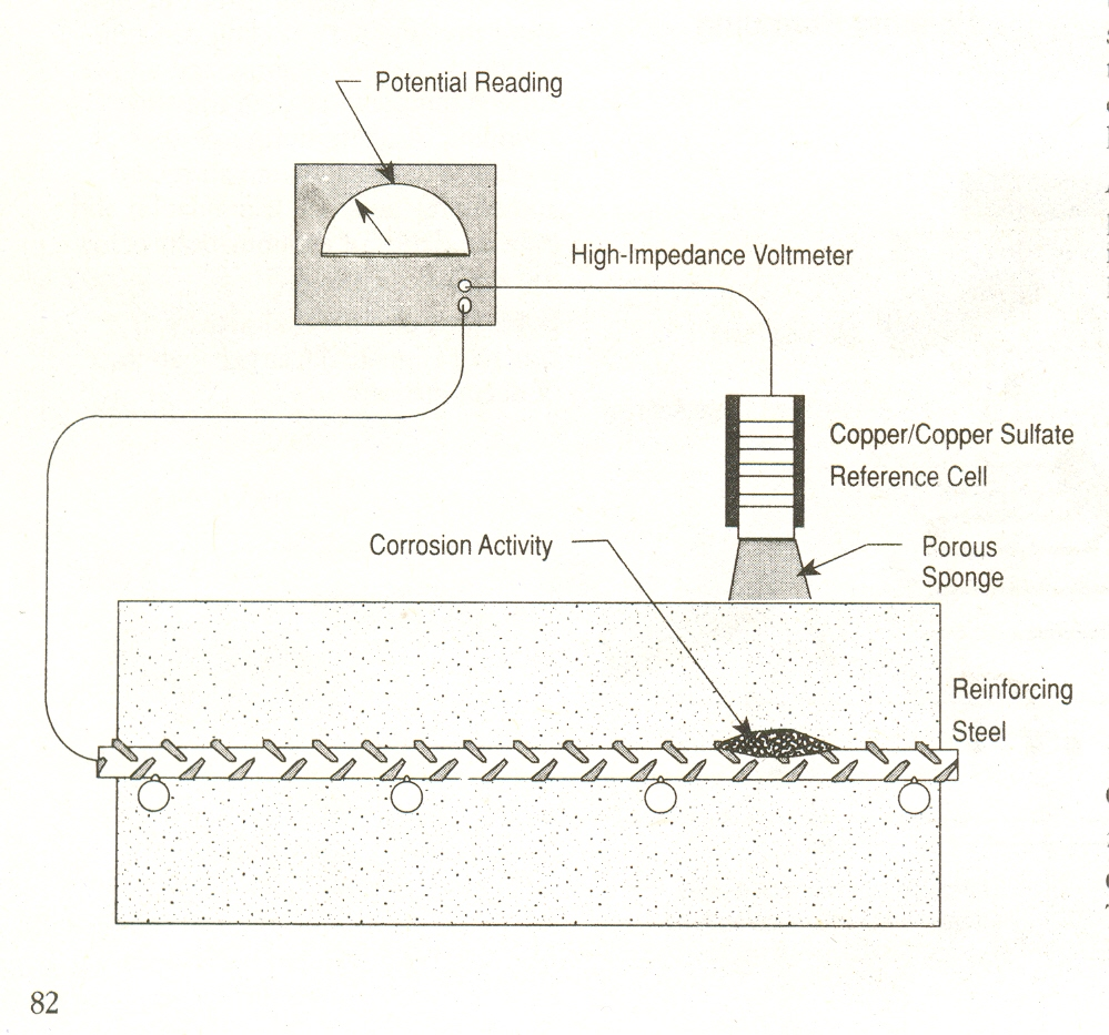
Half Cell Potentiometer to measure the corrosion activity
Chloride content
The concrete from the structural element is collected and sampling is done at various depths and analyzing for chloride ion content. The results indicate the depth of chloride ion ingress into the concrete.Depth of carbonation
Carbonation of concrete is the reaction among acidic gases from the air, moisture and the alkaline cement paste. To determine the depth of carbonation, a fresh concrete surface must be exposed by core sampling and splitting the core with hammer and chisel. The position of the carbonation front is measured by spraying the concrete surface with an acid based indicator which changes the colors at a pH of about 10, indicating the interface between carbonated and uncarbonated zones. Usually phenolphthalein in ethanol solution is used as a spray indicator.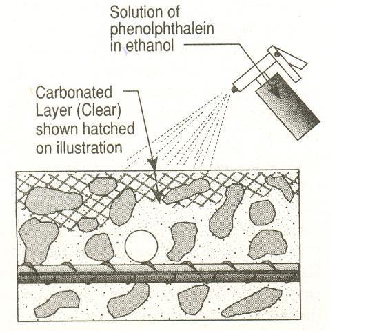
Fig.5 Assessment of depth of carbonation in the concrete
2.2.7 Petrographic Analysis
It is a detailed examination of concrete to determine the formation and composition of the concrete and to classify its type, condition and serviceability. To perform this type of analysis, concrete specimens are taken from the structure and are prepared by either polishing or etching a surface of the specimen. Petrographic examination includes identification of mineral aggregates, aggregate-paste inter-phase, assessment of the structure and integrity of the cement paste.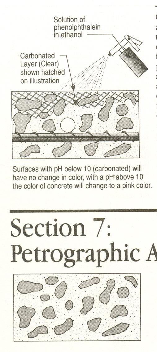
Fig.6 Petrographic examination of concrete
2.2.8 Dynamic response tests
These tests fall under the category of testing Integrity and Performance. These tests are conducted to assess the localized surface impacts to large-scale vibrations of elements or structures. Modal analysis, transient response and spectral analysis of surface waves (SASW) are all techniques in which responses at some position away from the impact point are measured, processed and analyzed to compare defects and layering effects. One technique gaining popularity is based on frequency-domain analysis of the reflected signals resulting from a surface impact. Features such as voids or delamination can be detected by a shift in the amplitude of higher frequency components of the return signal. Adjustment of the duration of the input impulse can be used, for example, to enhance or suppress the response from layer of reinforcing bars. This “impact-echo” technique has been used to monitor the thickness and integrity of concrete slabs and walls as well as cracking in beams and to detect air voids resulting from inadequate grouting of steel post-tensioning ducts.
Sub-surface radar is a technique / useful tool for testing structural concrete, which is non damaging and only required access to one surface thus enabling large areas to be inspected relatively quickly. The successful applications include determination of construction features and element thickness, location of buried features such as voids, location of moisture and salt contamination. A series of waveform pulses are transmitted into the concrete surfaces and results are generally presented in the form of a plot of the reflected signals obtained during a scan with amplitude and polarity identified by varying gray scales or colours. Interpretation relies on characteristic pattern recognition and although signal processing can clarify the images, there is a limit to what can be achieved with results from inappropriate apparatus settings. Where multiple features are involved such as closely spaced reinforcing bars, it becomes very difficult to identify particular features of interest.
2.2.9 Locating de-laminated concrete
Hammer sounding is the least expensive method. By striking we get solid and hollow sounds. Hollow sounds emanate from delaminated portions. IR thermography is a useful method of detecting delaminations in bridge decks. This method is also used for concrete components exposed to direct sunlight. The method works on the principle that as the concrete heats and cools, there is substantial thermal gradient within the concrete because concrete is a poor conductor of heat. De-laminations and other discontinuities interrupt the heat transfer through the concrete. These defects causes higher surfacetemperature than the surrounding concrete during periods of heating and a lower surface temperature than the surrounding concrete during cooling. The equipment can record and identify areas of de-lamination and indicate depth of de-laminations below the surface.
Fig.3 Hammer sounding technique to locate delaminations in concrete
2.2.10 Locating voids, cracks and honeycombs
- Impact Echo method: The impact technique works by impacting the concrete surface with a short
- duration stress pulse that is reflected from the defects and external boundaries back to a receiver
- (transducer). The signals received are converted into a frequency spectrum and are displayed on a
- computer screen. Artificial intelligence software is used to analyze these signals, predicting the
- probability and depth of defects.
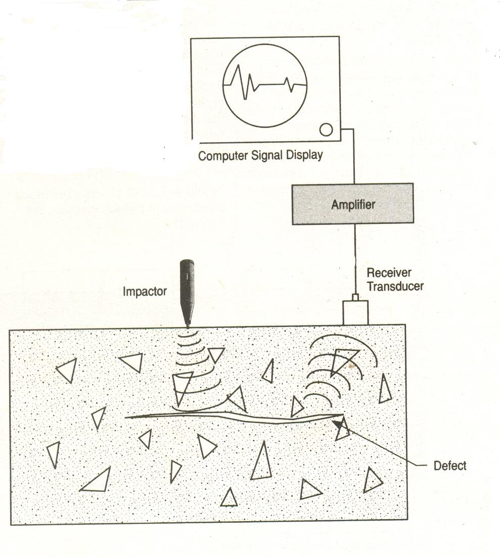
Impact Echo Technique
- Remote viewing inside a structure: Since access to certain parts of structures may be limited, remote
- viewing may be the only way to inspect these areas. Fiber optics (Borescope), video cameras, and
- periscopes are tools that allow for remote viewing.
2.2.11 Monitoring movements (cracks & deflections)
Monitoring movements in structures is important when assessing the behaviour of the structure in
response to changes in loads, temperature, internal conditions, and support at its foundation. The
monitoring of cracks can be conducted with various tools including optical comparators, glued glass
strips (tell-tales), glued in place crack gauges, LVDTs and extensometers.
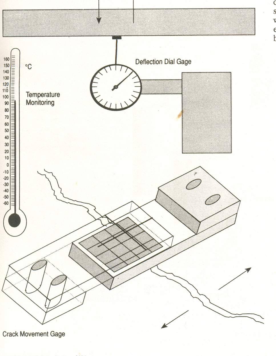
Movement monitoring of cracks
RESTORATION / REHABILITATION
After the thorough examination and testing of the structures elements, an in depth exploration is done regarding the data available about the structure, viz., drawings, designs, quality test reports, originally proposed aims / intent of the structure, etc. Then an appropriate repair or rehabilitation scheme is worked out, keeping in mind the prevention of distress in the system again in future. Before taking up the restoration / rehabilitation works, a cost-benefit analysis is made, which is nothing but the costs involved in restoring / rehabilitating the structure and the projected life of the structure. It depends upon the extent of damage to the structure, life of the structure, etc. Based on the techno-economic feasibility of the restoration / rehabilitation works, appropriate techniques and repair materials are used to rehabilitate the structure.SURFACE REPAIRS
It is a complex field and the type of repairs depend on a number of reasons because,
- Use of high performance concrete for new construction
- Precise designs
- Atmospheric pollution
- Wide range of repair materials as available
- More placement techniques are available
Major steps involved in surface repair are
- Repair analysis, strategy and design
- Material selection
- Reinforcing steel cleaning, repair and protection
- Bonding surface repairs to existing substrate
- Placement techniques
Material properties
Bond to substrate is the most important property to be considered for a repair material. If wrong materials are used / selected, it may result in loss of bond, de-lamination, detachment of repair from the substrate. Important properties to be looked for in this sense is tensile bond, low internal stress. To avoid high internal stress caused by thermal incompatibility, drying shrinkage, etc., materials with relevant properties compatible with the substrate should be selected for any repair work.
Types Of Repair Material
The various types of repair material used are
- Portland cement mortar
- Portland cement concrete
- Microsilica modified Portland cement concrete
- Polymer modified Portland cement mortar with non-sag filler
- Magnesium phosphate cement concrete
- Preplaced aggregate concrete (pozzolans as additives)
- Epoxy mortars
- Methyl methacrylate (MMA) concrete
- Shotcrete
Essential Properties of Repair Materials
Repair Material Ingredients
- Binder: It is the glue that binds all fillers and aggregates together to form a composite material. Ex: PPC, Epoxy, Acrylics
- Fine and Coarse Aggregates: Aggregates are used to reduce binder volume and enhance mechanical properties
- Special Fillers: These are used to fill in spaces left by the fine and coarse aggregates. Some fillers replace some quantity of cement. They are also used to improve internal cohesion.
- Polymer Modifiers: These are used to enhance the properties of material. Latex (SBR) is the most common. Other modifiers include acrylic, PVA and epoxy emulsions.
- Fiber reinforcement: Plastic or steel fiber reinforcement is used to add tensile strength and toughness to the repair material.
- Miscellaneous chemical modifiers: Miscellaneous modifiers are used to enhance and modify behaviour of the repair material. They include accelerators, retarders, shrinkage compensating additives, water reducers, flowability agents, expanding agents and air entraining admixtures.
3.1.4 General repair procedure (Joseph J Waddell, 1986)

Placement Procedures
The various methods that are generally adopted for the placing of the repair material over the base are as follows.
- Dry packing
- Form and cast in place
- Form and pump
- Grouted preplaced aggregates
- Full depth repair
- Dry mix shotcrete
- Wet mix shotcrete
- Overlays
STRENGTHENING AND STABILIZATION
When a concrete structure or member exhibits inadequate strength or stability, it may be feasible to
modify the structure using various stabilization and strengthening techniques. Strengthening is a
process of adding capacity to a member or structure. Stabilization is the process of halting a particular
unwanted situation from progressing. For example settlement of a structure can be stabilized by
grouting suitable chemicals to halt further movement. Concrete jacketing of an existing column to
add to the compressive load carrying capacity of an existing column is an example of strengthening.
Strengthening and stabilization techniques are generally considered to be either passive or active,
depending on how loads act on the additional components used to strengthen or stabilize the structure
(Ramesh, C.K., 1990). Techniques in which repairs do not participate in stress sharing until additional
loads (live or dead) are applied and / or until additional deformation occurs are called passive. There
are many situations in which additional deformation is not acceptable, i.e., the repairs must immediately
participate in stress sharing. These repairs are called active. Active systems require either prestressing
the repaired elements or temporarily removing the loads (both live and dead) from the existing elements,
or a combination of the two. Passive systems work well when live load changes are anticipated. For
example, upgrading a bridge to sustain heavier loads may require only a passive system. However, if a
member is overstressed, the only choice may be to use an active repair technique that will immediately
reduce the stress by sharing the loads, thus, eliminating the overstressed condition. The various
techniques of strengthening of members are summarized below.
Increasing stiffness / load carrying capacity
It is achieved by enlargement, which is nothing but placement of additional concrete and reinforcing
steel in the existing structural member. The enlargement is bonded to the existing concrete to create
a monolithic member.

Strengthening of column members
Composite construction: These are usually with fiber reinforced composite (FRC) material. The
jacketing method with steel or RCC is time consuming, dust prone, difficult to implement, and also
they add considerable / mass on the structure. FRC is found to alleviate all these problems. In
addition they have a very high specific strength (strength to weight ratio) and specific stiffness
(stiffness to weight ratio).
FRC wrapping for strengthening of RCC structures
Improving Moment Capacity of Beams
Usually, the moment capacity of beams is increased by providing external application of FRC plates
with fibres parallel to their longitudinal axes (Venkatesh, MS and Chandrashekar BN, 2005). Column
strength is improved by application of FRC wraps in circumferential direction of the element.
Post tensioning: It enhances a member’s ability to relieve overstressed conditions in tension, shear,
bending and torsion. This method can also be used to eliminate unwanted displacements in members
and to turn discontinuous members into continuous members.
Post tensioning methods of strengthening a member
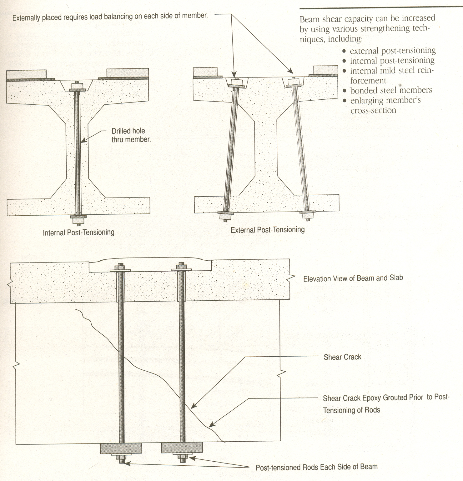
Beam shear strengthening
Methods include external post tensioning, internal post tensioning, internal MS reinforcement, bonded
steel members, enlarging member’s cross section, FRC retrofitting, addition of shear reinforcement, etc.

Shear strengthening of beams
Stress reduction techniques
Examples of stress reduction techniques are installing new Expansion joint in continuous concrete frame
and lateral ground movement isolation (by providing isolation bearings), which deforms during lateral
ground movement.
Shear capacity strengthening using shear collars
Shear stress occurs at the connection of floor systems and columns. When additional shear capacity is
required to resist punching shear, the following techniques are often used – column section enlargement,
composite bonded steel shear collars.
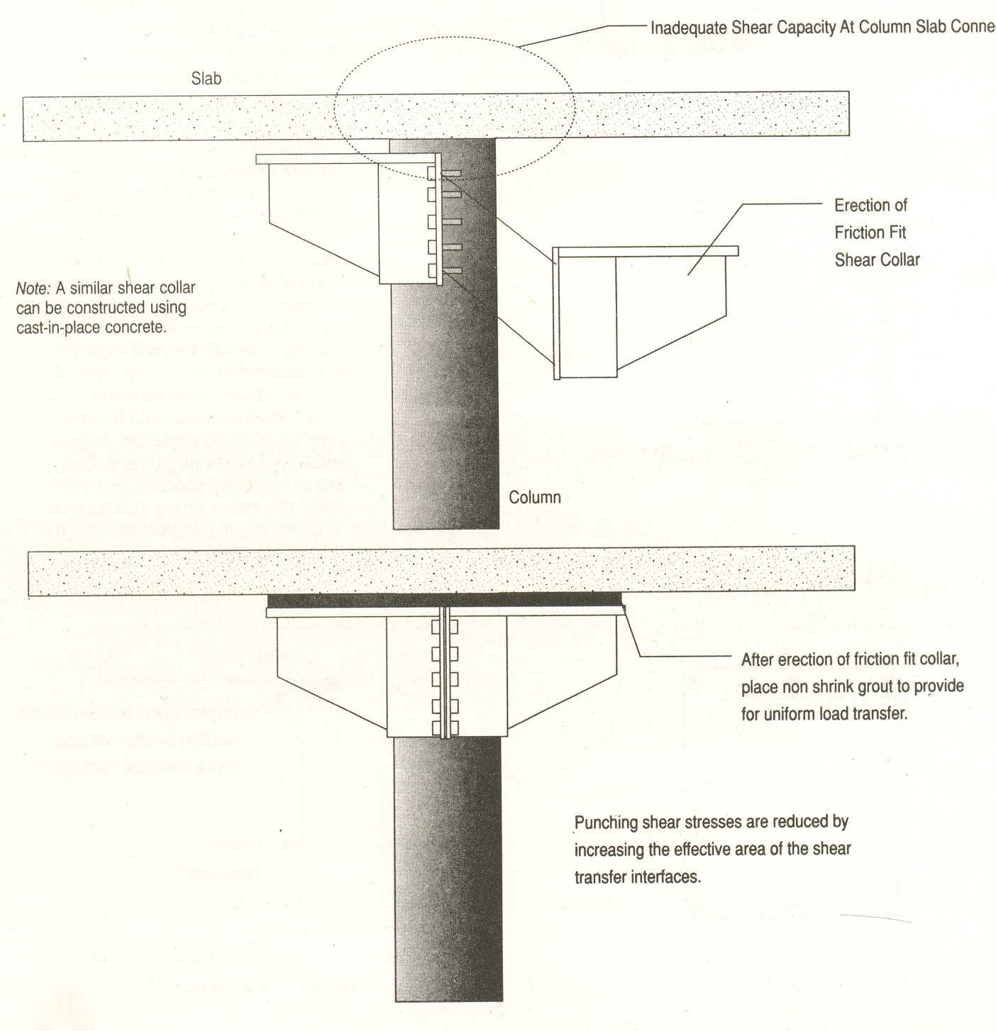
Increasing shear capacity of columns
Finally a protective layer / coating is provided with elastomers / epoxies or any other suitable materials
using various methods such as impregnation, painting, coating, etc.
CASE STUDY
(Restoration / Rehabilitation of a Multistoreyed Hotel Building) (Jagadish R, Sharada Bai, 1989)
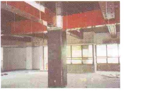
The hotel building was a eight storeyed structure and the construction was almost complete during the
investigation except for flooring and other finishing works. It consisted of basement floor, ground floor
plus six upper floors. The structure was basically a RC framed structure with brick masonry infill walls.
During the inspection of the building certain construction deficiencies were noticed (distress in the
elements). It was found that one of the corner columns at the ground floor level had failed by crushing
with surface concrete spalling and hollow sound emanating when tapped with a hammer. In addition,
some other columns at basement floor and ground floor had started showing signs of distress by splitting.
It was declared by the inspectors that the building was unsafe and the owners were asked to introduce
temporary supports around all distressed columns, for partially relieving them from the loads.
The original documents regarding the structure such as architectural drawings, structural drawings with
relevant structural design calculations, soil investigation report, quality reports were requested from the
owners. From the records and visual inspection, the following observations were made.
- The soil investigation report was not available, as no such investigation had been carried out. It was
informed that based on the physical observation of the soil, a value of 300 kN/m2 had been assumed as
the safe bearing capacity of soil.
- Structural design calculations were not furnished for scrutiny for the simple reason that the detailed design had not been done by the engineer. Only a few structural drawings of beams and slabs (unattested) were made available. It was surprising to find that the designer was not a qualified structural engineer but an architect – cum – contractor.
- Record of strength of concrete used in construction was not available since no concrete cubes were cast and tested at any time.
- Information regarding the quality of reinforcing steel used was not furnished.

Typical floor beams and columns layout
- Corner column F1 had already yielded at ground floor level, concrete was spalling out and could be
scooped out with trowel, and tapping tests indicated that the concrete had a lot of de-laminations within
(hollow sounds) (fig.15).
- On columns B2, C5, D5, F2, F3, F4, vertical cracks were clearly visible.
- Dowel bars had been provided for further addition of floors.
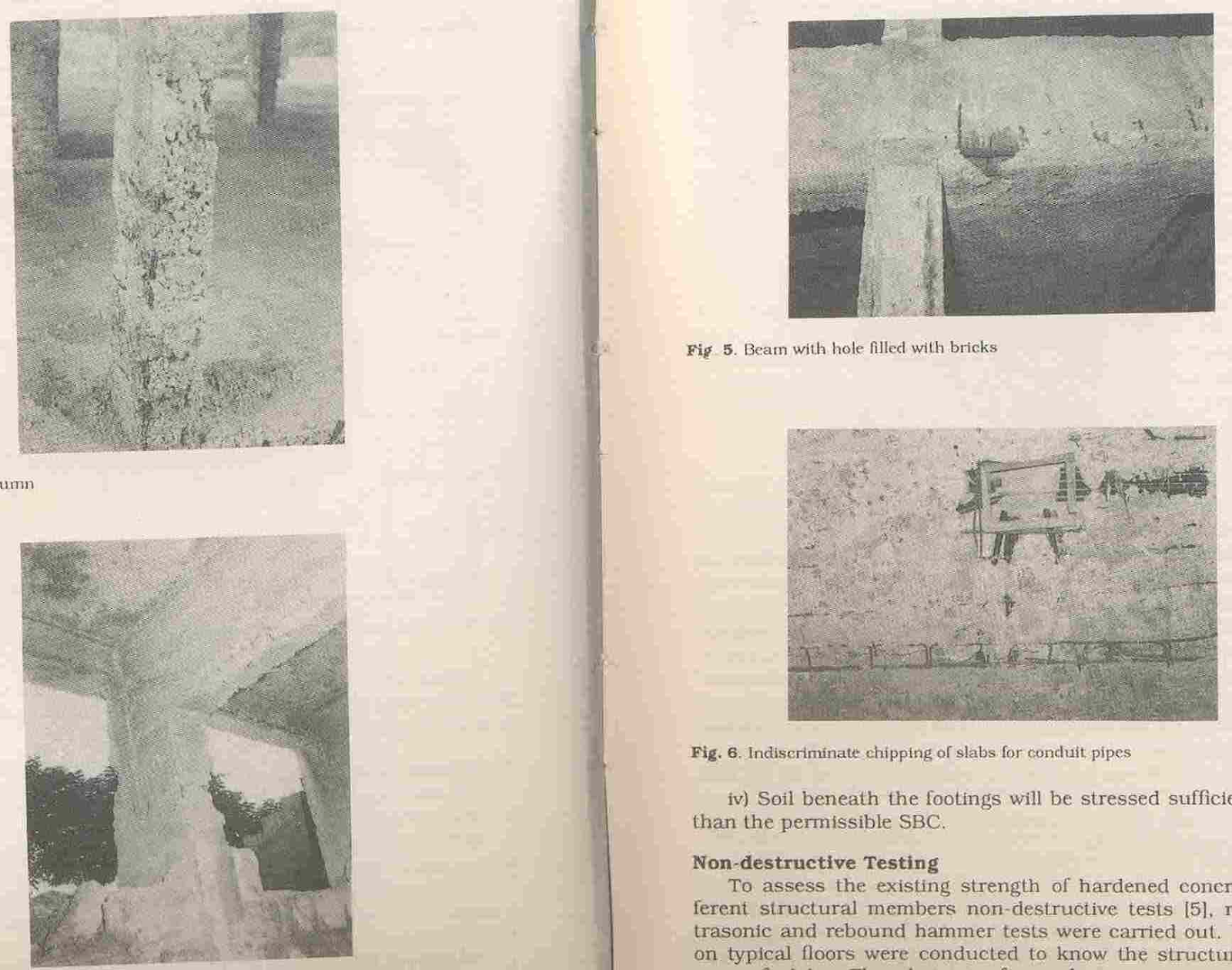

Damage to columns, beams and column-beam junctions
INVESTIGATIONS
Soil Investigation
A detailed soil investigation was conducted to evaluate the safe bearing capacity of soil at the existing
footing levels. It was found that the maximum value of SBC could only be 200kN/m2.
Load tests on Beams and Floors
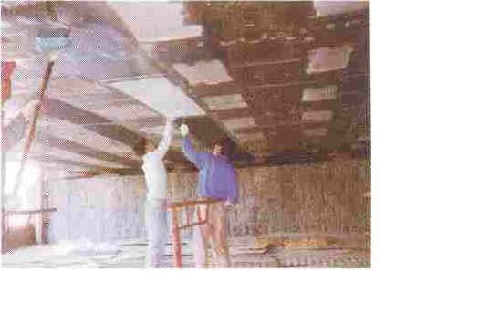
Load tests were conducted on a typical portion of actual floor as per the requirements in Clause 16 of
IS 456 – 1978, for verifying the structural soundness of slabs and beams at every floor level of the
building (fig.16). Sand bags of 0.5 kN weight were used for loading purposes. Maximum deflections
were measured using dial gauges of least count 0.01 mm at critical sections of beams and slabs after 24
hours of loading and recovery of deflections were also recorded wherever necessary. Measured
deflections were compared with the maximum allowable deflections. The experimental results revealed
that almost all the beams and slabs fulfilled the IS codal requirements and hence were declared as
structurally sound.
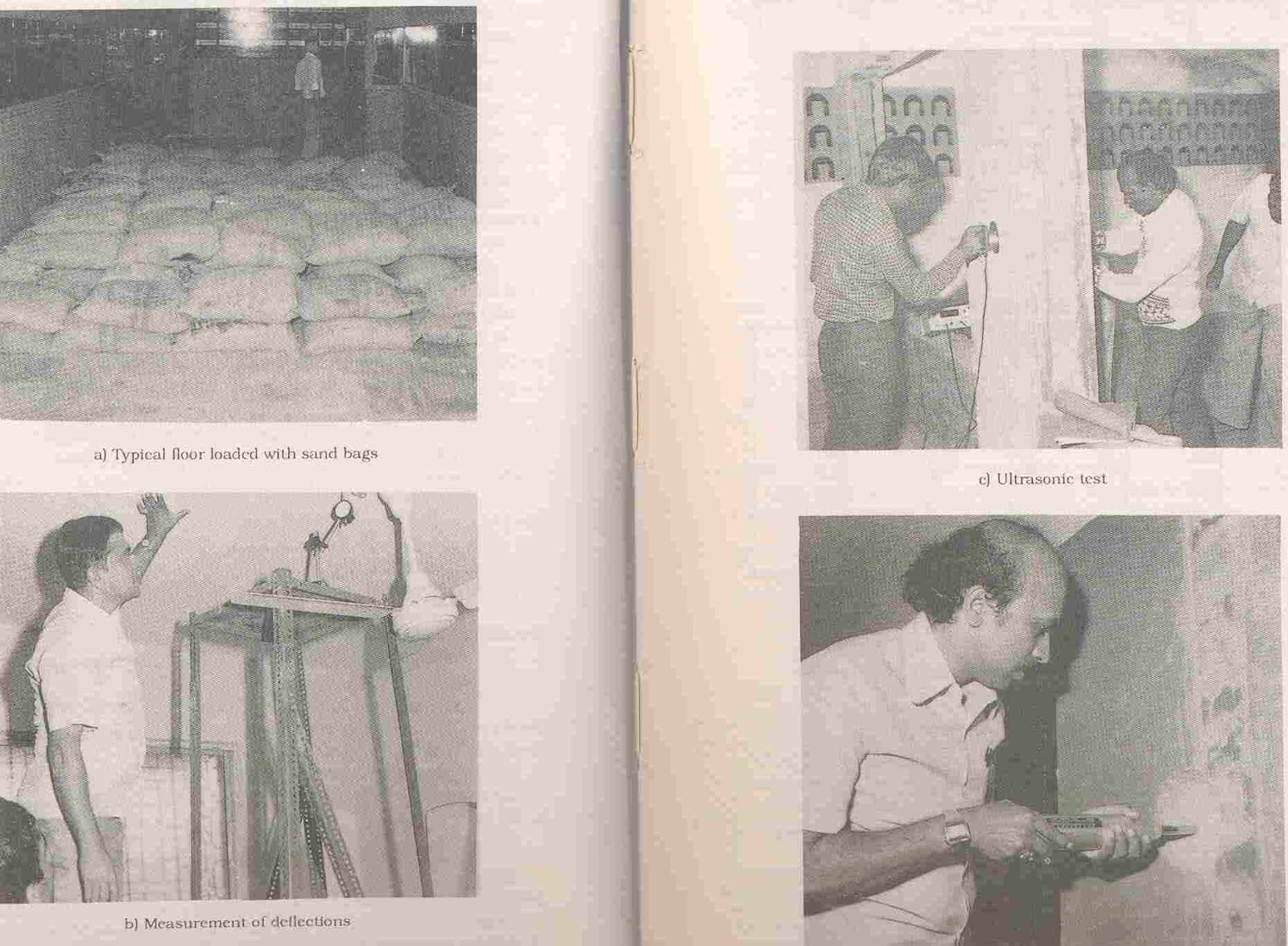

Load test on slabs and beams using sand bags and measurement of corresponding deflections
Non-Destructive Testing
Non-destructive testing of concrete, both rebound hammer test and ultrasonic tests were conducted on
columns and beams to assess the existing strength of hardened concrete.
From the results of rebound hammer test and ultrasonic tests conducted on columns and beams (fig.17)
it was noticed that the existing strength of concrete was generally in accordance with the assumed
strength of 20 N/mm2. However, in few columns, namely, F1,F2,F3,F4,B2,C2 and D2, the existing
strength was 10 to 20 % less than the required strength.

NDT of the structural elements using UPV meter and Rebound Hammer
DESIGN CHECK
After obtaining the above results, detailed analysis and design were made using the recommended
values of SBC of soil and actually existing concrete strength. The building was supposed to be a
lodging with 120 rooms. In the analysis, the loadings considered, over and above the self-weight of
slabs and beams, were
Live load - 2.0 kN/m2
Floor finish - 1.0 kN/m2
Ceiling plaster - 0.25 kN/m2
Equivalent uniformly distributed load to take care of the
partition walls on the slab – 1.5 kN/m2
Frames were analysed for the loading for critical loading. Structural members were redesigned based
on the limit state method as per IS 456-1978. the following observations were made from the analysis and
design.
- Corner column F1 had failed due to overstressing in addition to bad concreting.
- Columns B2,C5,D5,F2,F3,F4 in the basement and ground floors were not adequately designed for the loads coming on them.
- Columns in the first floor and above were found to be adequately reinforced for the existing concrete strengths.
- For the actual SBC of the soil, about 20 % of the total number of footings were overstressed particularly
- footings in rows D and E. Some of them as high as 50 to 100 %.
- Grid beams D6G6 had not been provided with adequate reinforcement.
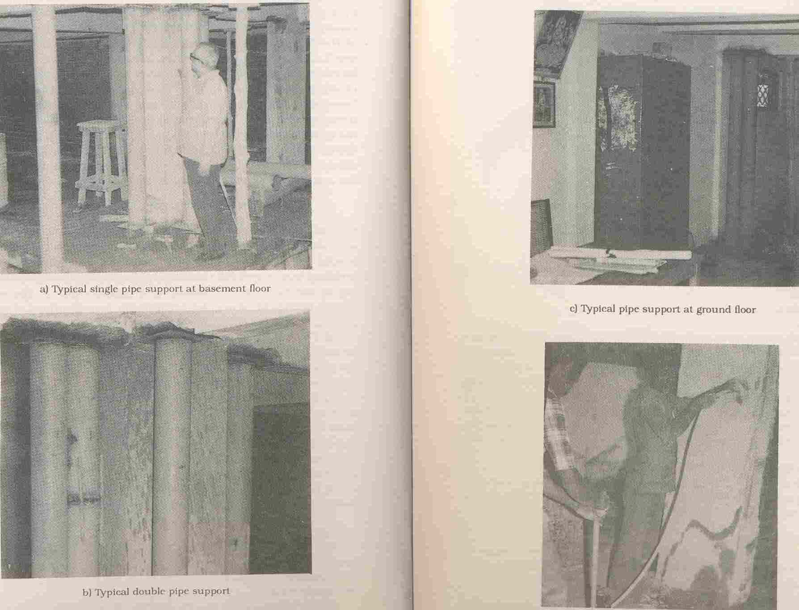
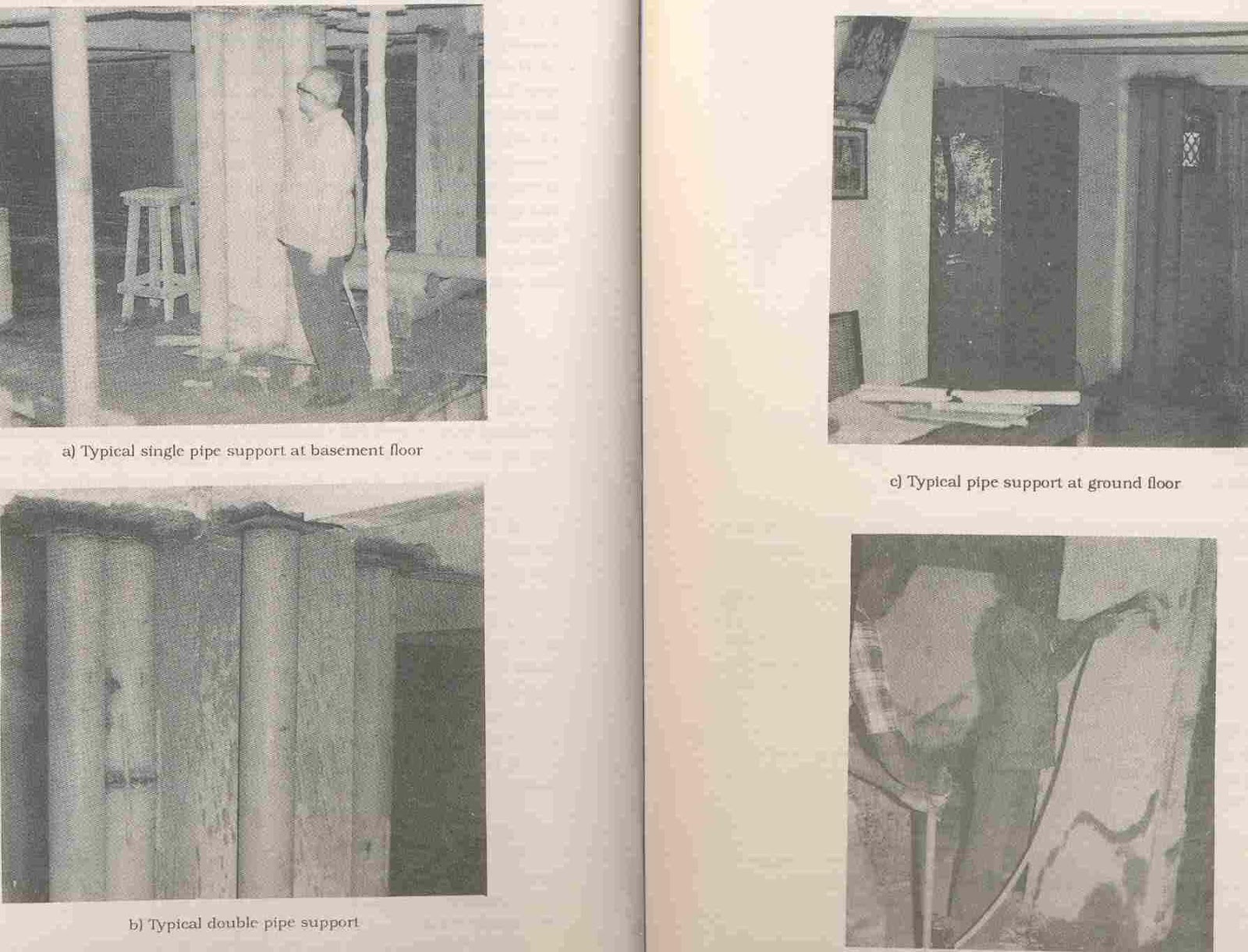
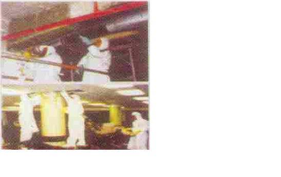
Beams being supported on MS twin pipes to relieve the loads on the columns and column grouting
in progress
RECTIFICATION SCHEME
After the thorough analysis, a techno-econimically feasible restoration scheme was prepared. The
details of the restoration / rehabilitation are summarized below.
- Over the entire height of the building 150 mm dia twin MS pipes were provided to support all the beams intercepting at the column to relieve the loads coming on columns and footings to be rectified. Typical supporting scheme are shown in the fig.18.
- GI pipes of diameter 75 mm were driven into the soil at 230 mm c/c around the footings which were identified as overstressed. Depth of piles varied from 2m to 3m depending upon the width of footings.
- All the piles were filled with M10 concrete.
- A pile cap of reinforced concrete was provided over the piles which were driven around the footings. This is shown in fig.19.
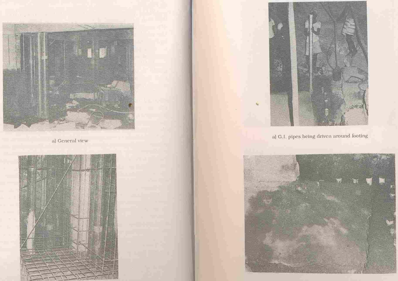
Rectification work in progress – piles in the form of 75 mm dia GI pipes and reinforcement for
pile cap
All such footings were leveled with plain concrete of M15 grade to make room for reinforcement of
the encased columns and the corresponding additional footing reinforcement as per design. This is
shown in fig.19.
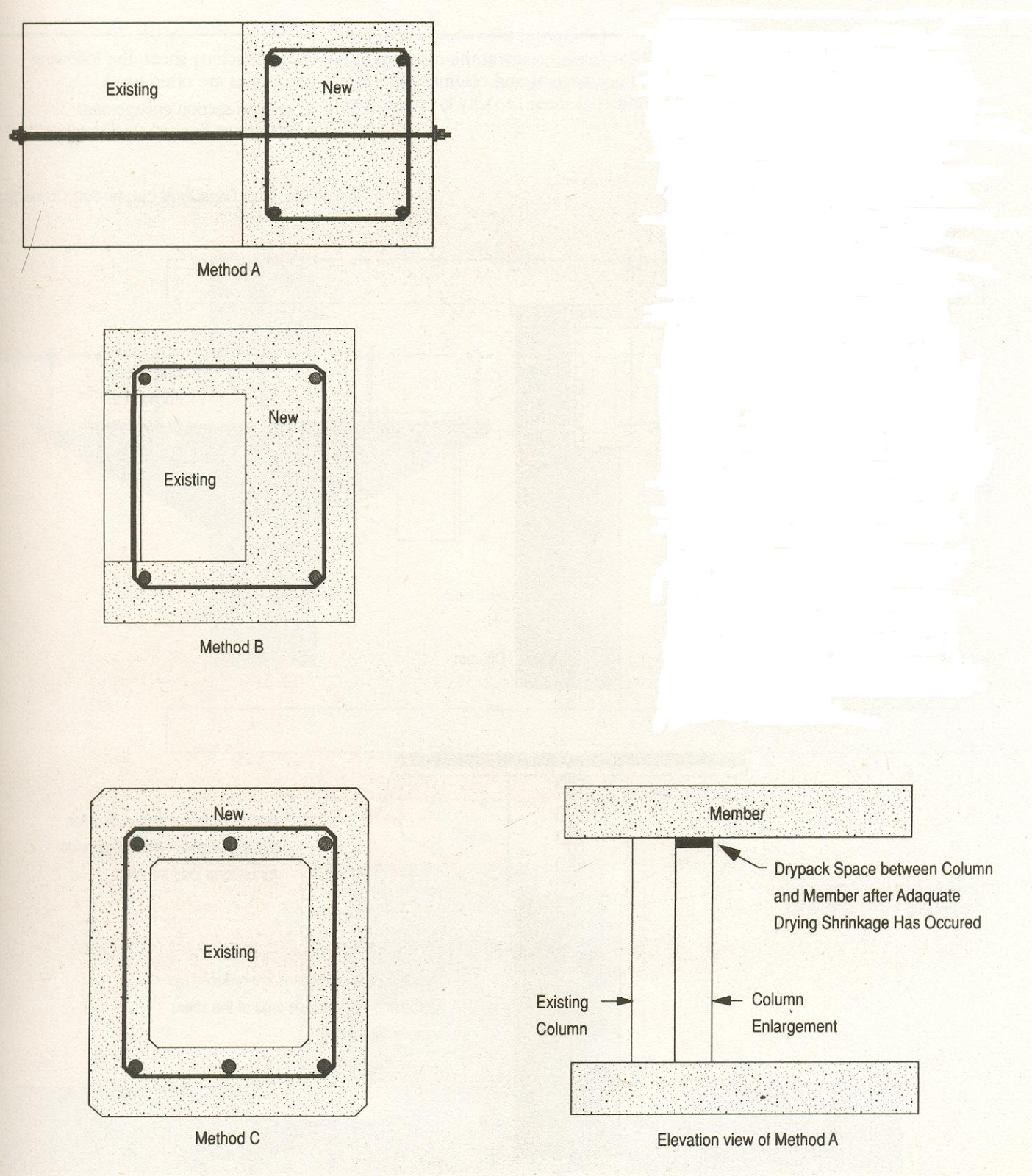
All distressed columns were encased with 100 mm thick reinforced concrete jackets as per design
requirements. Details of encasement of columns are shown in figure. Before the new concrete is
poured, the surface of the old existing column was hacked, all loose material removed and a coat of
epoxy paint was given. Reinforcement of the new jacket and old columns were connected by welding
16 mm dia shear-connectors between them at 500 mm c/c in a zigzag manner. The reinforcement
detailing of typical encased columns is shown in fig.20.

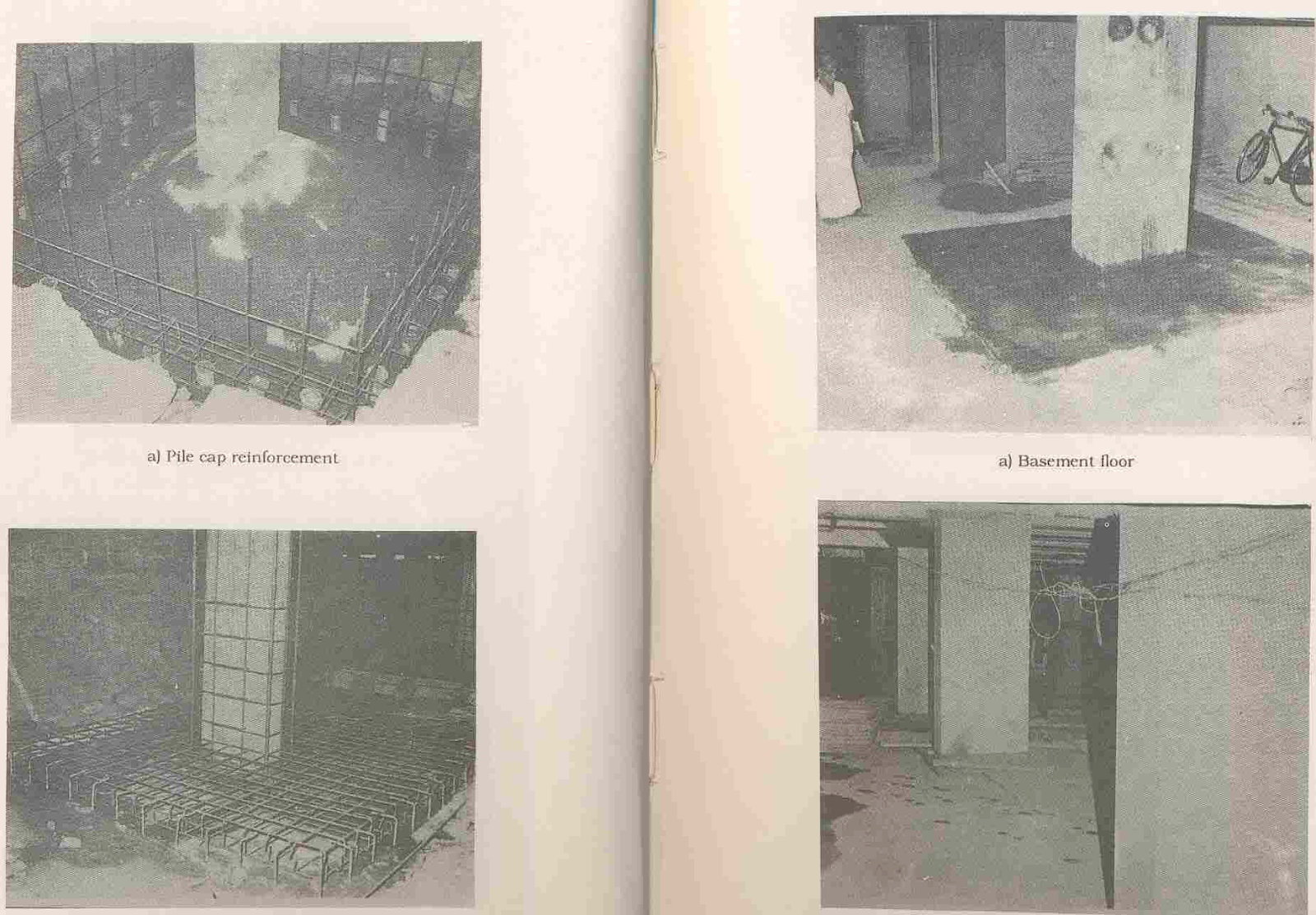
Rectification works – Pile capping, columns jacketing and finished column
- Corner column F1, which was supposed to have failed already had been supported by 150 mm diameter MS twin pipes up to the second floor level. The column was redesigned presuming its existing load carrying capacity was zero. Reinforced concrete wall 430 mm thick with adequate reinforcement as per design were provided. Twin pipes which were used as temporary supports were left undisturbed. Reinforcement detailing with the twin pipe supports is shown in figure20. Even though the column had failed in the ground floor, the rectification scheme was carried out right from basement extending up to second floor level.
All the honeycombed columns and beam-column joints were grouted as follows. Holes of 10 mm
diameter spaced at 500mm c/c were drilled over the entire height of the columns and at beam-column
joints. 10mm diameter PVC tubes were inserted into the drilled holes. A neat cement paste with
2 percent expansive cement as admixture was prepared as per the Manufacturer’s specifications.
The cement paste thus prepared was grouted under a pressure of 0.4 to 0.5 N/mm2 into the cavities of
the concrete until the paste refused to go in any more. The procedure was repeated for all columns
and beam-column junctions at all floors.
A new column of dimension 450 x 450 mm with appropriate footing as per the design requirement was
A new column of dimension 450 x 450 mm with appropriate footing as per the design requirement was
introduced at E6 for the grid beam D6E6G6 throughout the height of the building. This made the grid
beam to behave as a continuous beam. Existing reinforcement was found to be sufficient to make it
behave as a continuous beam.
The dowel bars of the columns extending beyond the terrace level were cut off to be flush with the
The dowel bars of the columns extending beyond the terrace level were cut off to be flush with the
terrace floor level and terrace was finished with weatherproof course.
Protective coatings, painting and other finishing works were carried out and the structure was put to
Protective coatings, painting and other finishing works were carried out and the structure was put to
service satisfactorily.
CONCLUSIONS
- Concrete structures are vulnerable to deterioration under a varied environment and hence requiresperiodic maintenance.
- Structural elements exhibit distress, such as rust spots, spalling, honeycombing, dampness, exposedreinforcement bars, etc., when the deterioration process initiates.
- These defects, if not taken care of during the early stages, will ultimately lead to the deterioration ofthe structure as a whole.
- Condition assessment is a tool by which the present condition of the structure is assessed to check theintegrity of the element and also the structure as a whole, so that it performs well during its service life.
- Visual inspection, Non-destructive tests and semi-destructive tests are conducted to assess the condition
- of the structure.
- Previous data regarding designs, drawings, quality checks, previous inspection reports, etc., arecollected and the results from the condition assessment tests are analyzed in detail to verify the integrity
- of the structure and if there is any need for any strengthening / stabilization of the structure, or repairs
- will just suffice.
- A cost benefit analysis is made keeping in mind the residual life of the structure and the costs that willbe incurred in rehabilitating the structure, before a decision is taken regarding the restoration schemes.
- Various repair materials have been introduced into the market for rectification of the defects in thestructure. But, the right repair material is to be chosen, so as to ensure its compatibility with the base structure. With regard to polymeric repair materials, many properties must be considered such as
before putting them into use, which may otherwise lead to unwanted stresses in the base structural element.
- Many techniques are available for strengthening / stabilization of structures. Although Steel jacketingand concrete jacketing were the popular methods for increasing the load carrying capacity of any
many beneficial properties, such as ease of handling, high strength to weight ratio, insignificant contribution
to the increase in dead weight, etc. But the economy of using such a system should be critically evaluated
before adopting it as a restoration / rehabilitative measure.
- From the case study, the importance of the thorough designing for the requirements is stressed upon,which otherwise would increase the construction costs of the project substantially, as repairs /
- Buildings under distress can be effectively rehabilitated by adopting suitable strengthening techniquessuch as foundation strengthening by adding of piles, improving the load carrying capacity of columns
- Condition assessment and rehabilitation of structures is gaining importance in Indian context, especiallyin bridges, which were mostly built immediately after independence, and which are also nearing their


